 Business License

ADS1115: 16-Bit ADC for Raspberry Pi & Arduino | Practical Guide
By QIXINWEI | TI ADS1115 | Data Converters
Key Takeaways
The ADS1115 is a 16-bit delta-sigma ADC from Texas Instruments with four single-ended or two differential inputs, a programmable gain amplifier, and an I2C interface. It is the standard way to add precision analog measurement to a Raspberry Pi, which has no built-in ADC, and to upgrade the 10-bit ADC on an Arduino.
The programmable gain amplifier is the feature that matters most. It sets the full-scale range from ±6.144V down to ±0.256V, so a small sensor signal can fill the whole 16-bit range instead of using a fraction of it.
Data rate is programmable from 8 to 860 samples per second. Higher rates trade noise for speed, and the effective resolution drops at the fastest rates, so most precision designs run at 128 SPS or below.
Four pin-selectable I2C addresses (0x48 to 0x4B) allow up to four ADS1115 chips on one I2C bus, giving 16 single-ended channels from a single two-wire interface.
QIXINWEI supplies original TI ADS1115 converters in VSSOP-10, X2QFN-10, and SOT-5X3 packages, with bulk supply and BOM matching for production volumes.
Why the ADS1115 Exists
Most microcontrollers have a built-in ADC, but the built-in one is usually the weakest part of the chip. The Raspberry Pi has no ADC at all. The Arduino Uno has a 10-bit ADC, which gives 1024 steps across 5V, or about 4.9mV per step. That is fine for reading a potentiometer, but it is not enough for a load cell, a thermocouple, a pH probe, or a battery monitor that needs to resolve millivolts.
The ADS1115 solves this with a dedicated 16-bit delta-sigma converter. Sixteen bits gives 65,536 steps. With the programmable gain amplifier set to the ±0.256V range, one step is 7.8125µV. That is roughly 600 times finer than the Arduino's built-in ADC, and it comes with a proper low-drift internal voltage reference and oscillator already inside the chip, so the measurement does not drift with the supply voltage.
The ADS1115 is also a complete signal chain in a tiny package. The input multiplexer, the programmable gain amplifier, the voltage reference, the oscillator, and a digital comparator are all integrated. The designer adds the chip, two pull-up resistors on the I2C lines, and a decoupling capacitor, and the analog front end is done.
ADS1115 Key Specifications
Manufacturer: Texas Instruments
Converter type: 16-bit delta-sigma ADC with internal reference and oscillator
Resolution: 16 bits
Data rate: 8 SPS to 860 SPS, programmable
Input channels: 4 single-ended or 2 differential, multiplexed
PGA full-scale ranges: ±6.144V, ±4.096V, ±2.048V, ±1.024V, ±0.512V, ±0.256V
Interface: I2C, four pin-selectable addresses (0x48, 0x49, 0x4A, 0x4B)
Supply voltage: 2.0V to 5.5V
Current consumption: 150µA in continuous-conversion mode, auto shut-down in single-shot mode
Power consumption: 0.3mW typical
Comparator: Programmable digital comparator for undervoltage and overvoltage detection
Operating temperature: −40°C to +125°C
Packages: X2QFN-10 (2.0 × 1.5mm), VSSOP-10 (3.0 × 4.9mm), SOT-5X3 (2.9 × 2.8mm)
Related parts: ADS1113 (single differential input, no PGA), ADS1114 (single differential input, with PGA)
Single-Ended vs Differential: Which Input Mode to Use
The ADS1115 has four analog input pins, AIN0 through AIN3, and an internal multiplexer that connects them to the converter in different combinations. The choice between single-ended and differential mode is the first design decision, and it affects noise rejection directly.
Single-ended mode: Each input is measured against ground, giving four independent channels. This is the simplest wiring and the right choice for sensors that are already ground-referenced, such as potentiometers, photoresistors, and battery voltage dividers.
Differential mode: Two inputs are measured against each other, giving two channels. The converter measures only the difference between the pins, so any noise that appears equally on both wires cancels out. This is the right choice for bridge sensors, load cells, thermocouples, and current shunts, where the signal is small and the environment is noisy.
A practical rule: if the sensor has two wires and the signal is the voltage between them, use differential. If the sensor has one signal wire and a ground, use single-ended. The ADS1115 can mix modes in software by reconfiguring the multiplexer between conversions, but each conversion uses one mode at a time.
Setting the PGA Range
The programmable gain amplifier sets the full-scale input range, and it is the single most important setting on the ADS1115. The full-scale ranges are ±6.144V, ±4.096V, ±2.048V, ±1.024V, ±0.512V, and ±0.256V, selected by the PGA bits in the configuration register.
The rule is simple: pick the smallest range that still covers the largest signal you expect. A 0 to 100mV load cell signal measured on the ±6.144V range uses less than 2 percent of the converter's range, wasting most of the 16 bits. The same signal on the ±0.256V range uses nearly 40 percent of the range, giving roughly 25 times more effective resolution.
One warning: the PGA range sets the differential full-scale voltage, but the absolute voltage on any input pin must stay within ground and the supply voltage. A ±0.256V range does not mean the input can go negative. The ADS1115 measures a differential signal, but each pin must remain between GND and VDD. A sensor that swings below ground needs level shifting or a different front end.
LSB size at ±6.144V range: 187.5µV
LSB size at ±4.096V range: 125µV
LSB size at ±2.048V range: 62.5µV
LSB size at ±1.024V range: 31.25µV
LSB size at ±0.512V range: 15.625µV
LSB size at ±0.256V range: 7.8125µV
Data Rate: Speed vs Noise
The ADS1115 data rate is programmable from 8 to 860 samples per second. The delta-sigma converter averages the input over each conversion period, so a slower rate averages more samples and produces a quieter result. At 8 SPS the output is the cleanest; at 860 SPS it is the noisiest.
The effective number of bits drops at high data rates. At the maximum rate of 860 SPS with the smallest ±0.256V range, the effective resolution falls to around 13.8 bits, not 16. That is still far better than a 10-bit built-in ADC, but it means the fastest setting is not the most precise one.
For most sensor monitoring, 128 SPS is a good default. It is fast enough for temperature, pressure, battery voltage, and slow industrial signals, and quiet enough to use most of the 16-bit range. Use 860 SPS only when the signal genuinely changes fast, such as audio-band vibration or fast current transients, and accept the extra noise.
Wiring the ADS1115 to Raspberry Pi and Arduino
The ADS1115 connects over I2C with four wires plus power: VDD, GND, SCL, and SDA. The ALERT/RDY pin is optional and connects to a GPIO if the design uses the comparator or conversion-ready interrupt.
Raspberry Pi: Connect VDD to 3.3V, GND to ground, SCL to GPIO3, SDA to GPIO2. The Pi's I2C bus already has pull-up resistors. The default I2C address is 0x48 with the ADDR pin grounded. The Adafruit ADS1x15 library and the CircuitPython library both support the ADS1115 directly.
Arduino: Connect VDD to 5V or 3.3V, GND to ground, SCL to A5, SDA to A4 on an Uno, or to the dedicated SCL/SDA pins on newer boards. Add 4.7kΩ pull-up resistors on SCL and SDA if the board does not already have them. The Adafruit ADS1x15 Arduino library supports the ADS1115 directly.
I2C address: The ADDR pin selects one of four addresses: GND gives 0x48, VDD gives 0x49, SDA gives 0x4A, SCL gives 0x4B. Up to four ADS1115 chips can share one I2C bus, giving 16 single-ended channels.
Decoupling: Place a 0.1µF ceramic capacitor close to the VDD pin. Keep the analog input traces short and away from digital switching signals, and keep the I2C pull-up resistors close to the chip.
Common ADS1115 Mistakes
1. Leaving the PGA at the default range
The default full-scale range is ±6.144V. Most sensor signals are far smaller, so leaving the default wastes most of the converter's resolution. Always set the PGA to the smallest range that covers the expected signal.
2. Measuring a floating input
An unconnected ADS1115 input floats and returns random values. Every input pin that is not in use should be tied to ground, or the multiplexer should be configured to skip it. A floating channel can also couple noise into the channel being measured.
3. Exceeding the absolute input range
The PGA range is differential, but each input pin must stay between GND and VDD. A sensor output that goes below ground, or above the supply, will clip or damage the input. Check the absolute voltage on each pin, not just the differential voltage.
4. Running at 860 SPS for a slow signal
The maximum data rate is tempting, but it adds noise for no benefit when the signal changes slowly. A temperature sensor does not need 860 samples per second. Run at 128 SPS or below for the cleanest readings.
5. Sharing the I2C bus without checking addresses
The ADS1115 default address is 0x48, which is shared by several other common I2C parts. If another device on the bus uses 0x48, move the ADS1115 to 0x49, 0x4A, or 0x4B by changing the ADDR pin connection.
Where the ADS1115 Fits
Battery monitoring: The 16-bit resolution and PGA make the ADS1115 ideal for measuring battery voltage and current through a shunt, with enough precision to track state of charge.
Load cells and strain gauges: Differential mode with the ±0.256V PGA range reads bridge sensors directly, making the ADS1115 the standard choice for weighing scales and force measurement.
Temperature sensing: Thermocouples and RTDs produce millivolt signals that the ADS1115 resolves cleanly, especially in differential mode with the small PGA ranges.
Industrial data acquisition: The −40°C to +125°C operating range, the digital comparator for threshold alarms, and the low 150µA current suit remote sensors and battery-powered field equipment.
Raspberry Pi sensor hats: The ADS1115 is the most common ADC on Raspberry Pi sensor boards, because the Pi has no built-in ADC and the ADS1115 needs only two I2C wires.
ADS1115 FAQ
What is the ADS1115?
The ADS1115 is a 16-bit delta-sigma analog-to-digital converter from Texas Instruments with four single-ended or two differential inputs, a programmable gain amplifier, an I2C interface, and an internal voltage reference. It adds precision analog measurement to microcontrollers and single-board computers.
What is the difference between ADS1115 and ADS1015?
The ADS1115 is 16-bit with a maximum data rate of 860 SPS. The ADS1015 is 12-bit with a maximum data rate of 3300 SPS. Choose the ADS1115 for precision and the ADS1015 for speed.
Can I connect multiple ADS1115 chips to one I2C bus?
Yes. The ADDR pin selects one of four I2C addresses, 0x48, 0x49, 0x4A, and 0x4B, so up to four ADS1115 chips can share one bus, giving 16 single-ended channels.
What is the smallest voltage the ADS1115 can measure?
With the PGA set to the ±0.256V range, one LSB is 7.8125µV. In practice the usable resolution depends on noise, and the effective number of bits drops at high data rates, so most designs achieve 13 to 15 effective bits.
Does the ADS1115 work with 3.3V and 5V systems?
Yes. The supply range is 2.0V to 5.5V, so the ADS1115 works directly with both 3.3V Raspberry Pi systems and 5V Arduino systems. The input pins must stay within ground and the supply voltage.
What is the ADS1115 used for?
Common uses are battery monitoring, load cells and weighing scales, temperature sensing with thermocouples and RTDs, industrial data acquisition, and adding analog inputs to the Raspberry Pi. The combination of 16-bit resolution, PGA, and I2C makes it the default precision ADC for maker and industrial sensor designs.
Sourcing the ADS1115 from QIXINWEI
QIXINWEI supplies original Texas Instruments ADS1115 converters in VSSOP-10, X2QFN-10, and SOT-5X3 packages, along with the ADS1113 and ADS1114 variants and the 12-bit ADS1015, in prototype quantities through production volumes. As a full-range electronic components distributor with BOM matching service, QIXINWEI can consolidate the ADS1115 with the sensors, microcontrollers, and passive parts on your bill of materials into a single shipment. For a quotation or availability check, contact the QIXINWEI sales team with the required package, quantity, and target price.
Supplier: Shenzhen Qixinwei Technology Co., Ltd. (QIXINWEI)
Website: https://www.qixinwei-pcba.com/
Recently Posted
-
INA226AQDGSRQ1: A 16-Bit Current and Power Monitor for Automotive Power Rails
November 20, 2026A power rail in an automotive system is only as reliable as the measurement behind it. When a battery management system, an ADAS d Read More
-
ATmega32U4-AU: Microchip 8-Bit AVR MCU with Native USB
November 18, 2026Key TakeawaysWhat it is: The ATmega32U4-AU is Microchip's 8-bit AVR microcontroller with a built-in USB 2.0 device controller, Read More
-
DRV8889QWRGERQ1: TI Automotive Stepper Driver with 1/256 Microstepping
November 14, 2026Key TakeawaysThe DRV8889QWRGERQ1 is a Texas Instruments AEC-Q100 qualified stepper motor driver for automotive bipolar stepper mot Read More
-
STC89C52 vs AT89S52: Two Classic 8051 MCUs — Which One Should You Choose?
November 12, 2026By QIXINWEI | STC89C52 vs AT89S52 | Classic 8051 MCU ComparisonThe STC89C52 and the AT89S52 look alike on paper: the same name str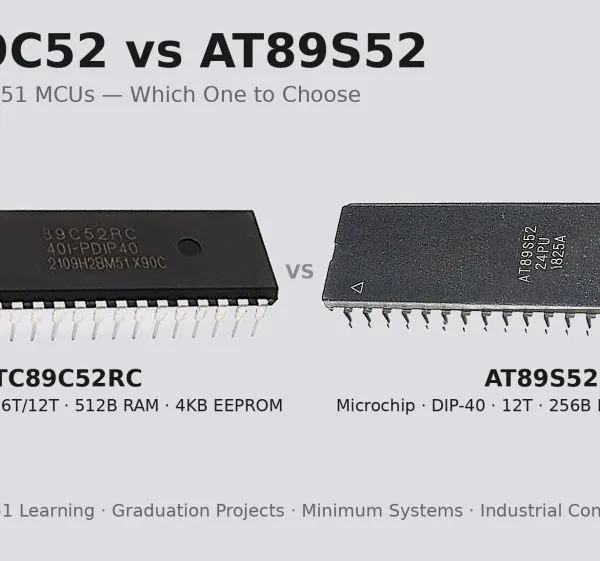 Read More

Contact Us
Recommended Products
-
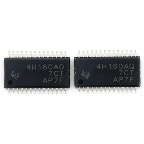
 TPS4H160BQPWPRQ1 Original TI Automotive Quad-Channel 160mOhm Smart High-Side Switch HTSSOP-28NegotiableMOQ: 100 Units
-
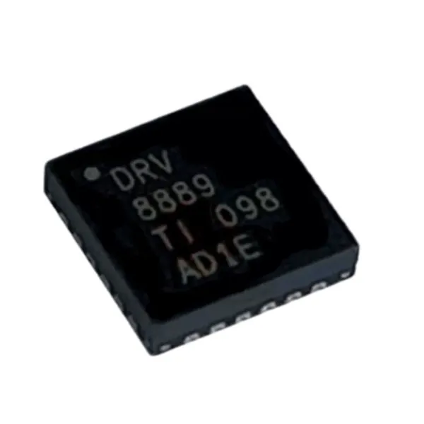
DRV8889QWRGERQ1 Original TI Automotive Stepper Motor Driver 2.4A 45V VQFN-24NegotiableMOQ: 100 Units
-
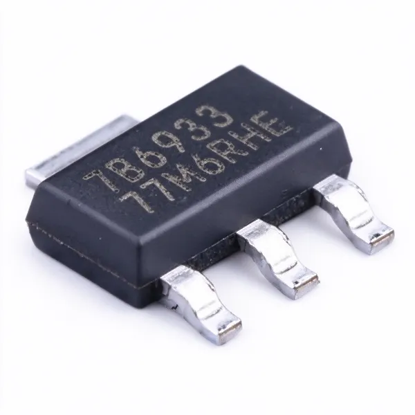
TPS7B6933QDCYRQ1 Original TI Automotive 3.3V 150mA 40V LDO Linear Regulator SOT-223NegotiableMOQ: 100 Units
-
INA226AQDGSRQ1 Original TI Automotive 36V 16-Bit I2C Current Power Monitor VSSOP-10NegotiableMOQ: 100 Units
-
TPS7A6650QDGNRQ1 Original TI Automotive 150mA 40V LDO Linear Regulator 5V Fixed Output HVSSOP-8NegotiableMOQ: 100 Units
-
Microchip PIC18F4550-I/P 8-Bit MCU 48MHz 32KB Flash USB 2.0 DIP-40NegotiableMOQ: 100 Units
-
Espressif ESP32-C3 RISC-V WiFi Bluetooth LE Microcontroller 160MHz 400KB SRAM QFN-32NegotiableMOQ: 100 Units
-
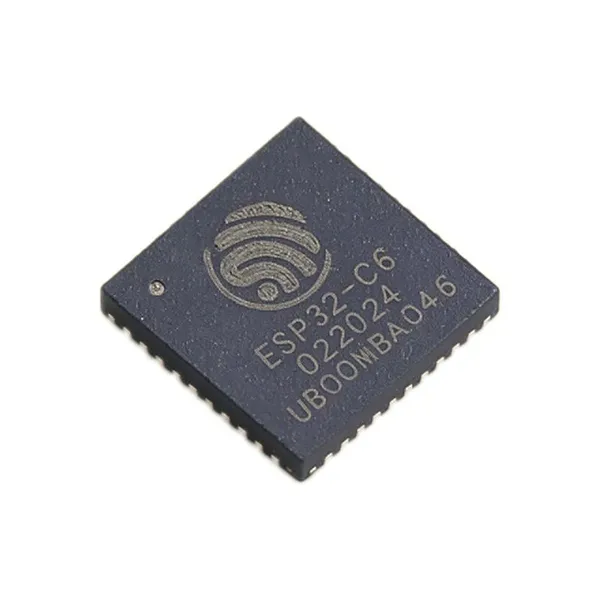
ESP32-C6 RISC-V WiFi 6 + Bluetooth 5.3 LE + Zigbee/Thread SoC 160MHz 512KB SRAM QFN-40 IoT Smart HomeNegotiableMOQ: 100 Units
-
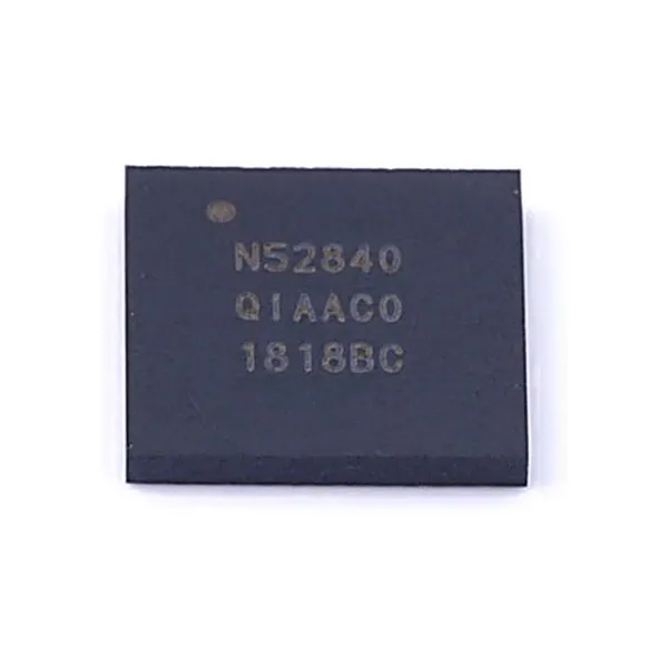
NRF52840 Nordic Bluetooth 5.3 SoC Cortex-M4F 64MHz 1MB Flash 256KB RAM AQFN-73NegotiableMOQ: 100 Units
-
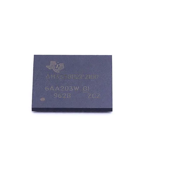
AM3358 TI Sitara AM3358BZCZ100 ARM Cortex-A8 Processor 1GHz BGA-324NegotiableMOQ: 100 Units
-
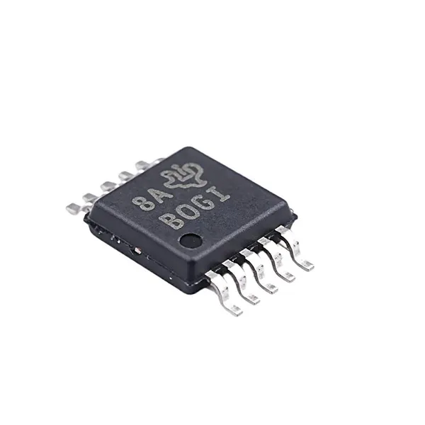
ADS1115 Texas Instruments ADS1115IDGSR 16-Bit ADC 860 SPS PGA I2C VSSOP-10NegotiableMOQ: 100 Units
-
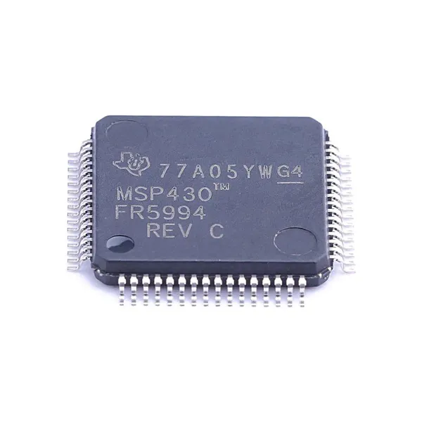
MSP430FR5994 TI MSP430FR5994IPM Ultra-Low-Power MCU 16MHz 256KB FRAM LEA LQFP-64NegotiableMOQ: 100 Units
-
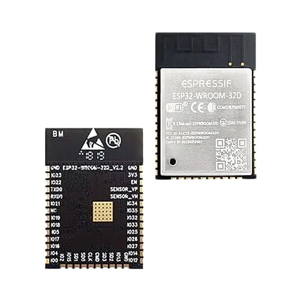
Espressif ESP32-WROOM-32D WiFi Bluetooth Module Dual-Core 240MHz 4MB Flash PCB Antenna IoTNegotiableMOQ: 100 Units
-
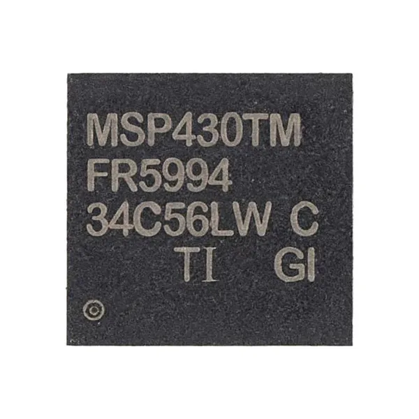
MSP430FR5994 TI MSP430FR5994IRGC Ultra-Low-Power MCU 16MHz 256KB FRAM LEA VQFN-64NegotiableMOQ: 100 Units
-
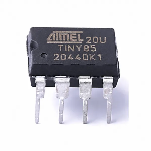
ATtiny85-20PU 8-Bit AVR Microcontroller 20MHz 8KB Flash 512B SRAM DIP-8NegotiableMOQ: 100 Units
-
Microchip ATmega2560-16AU AVR 8-Bit MCU 16MHz 256KB Flash 8KB SRAM TQFP-100NegotiableMOQ: 100 Units
-
Nordic Semiconductor NRF52832-QFAA Bluetooth 5 SoC ARM Cortex-M4F 64MHz 512KB Flash 64KB RAM QFN-48NegotiableMOQ: 100 Units
-
ATmega32U4-AU Microchip 8-Bit AVR MCU 16MHz 32KB Flash 2.5KB SRAM USB TQFP-44NegotiableMOQ: 100 Units
-
Microchip PIC16F877A-I/P 8-bit PIC MCU 20MHz 14KB Flash 368B RAM DIP-40NegotiableMOQ: 100 Units
-
STMicroelectronics STM32F103C8T6 ARM Cortex-M3 MCU 72MHz 64KB Flash 20KB SRAM LQFP-48NegotiableMOQ: 100 Units