 Business License

STC89C52 vs AT89S52: Two Classic 8051 MCUs — Which One Should You Choose?
By QIXINWEI | STC89C52 vs AT89S52 | Classic 8051 MCU Comparison
The STC89C52 and the AT89S52 look alike on paper: the same name structure, the same package, both 8KB of Flash, both 8051 cores. Many people assume they are interchangeable. Solder one in place of the other and it will run — but the differences are everywhere: speed, memory, programming, pins. This article compares them one by one against the official datasheets, with the numbers and their sources.
Key Takeaways
Speed: the STC89C52RC switches to 6T mode — one machine cycle takes 0.54 µs with an 11.0592MHz crystal, half the AT89S52's 1.09 µs. Same crystal, twice the speed.
Memory: Flash is 8KB on both. RAM is 512 bytes on the STC against 256 on the AT89S52, and the STC adds 4KB of built-in EEPROM the AT89S52 does not have — no external chip needed to store parameters.
Programming: the STC programs over UART ISP with a single USB-to-serial cable and the STC-ISP software; the AT89S52 programs over SPI ISP and needs an SPI programmer — a serial cable cannot program it.
Pinout: both are DIP-40 with the same standard 8051 layout and a fully compatible instruction set, so code runs on either — but the STC has 3 extra P4 I/Os and 2 extra external interrupts, and the programming interfaces differ, so a swap is not always a drop-in.
Speed: 6T vs 12T Is a Different Game
A classic 8051 machine cycle takes 12 clocks. The AT89S52 follows that rule and nothing else — one machine cycle is 12 clocks, no option to change it. The STC89C52RC is different: it can switch to 6T mode, where one machine cycle takes only 6 clocks.
STC89C52RC machine cycle: 6T / 12T selectable (STC official datasheet)
AT89S52 machine cycle: 12T only (Microchip datasheet 1919D)
11.0592MHz crystal, 12T mode: machine cycle 1.085 µs
11.0592MHz crystal, 6T mode: machine cycle 0.54 µs
STC89C52RC maximum frequency: 48MHz (12T), 24MHz (6T)
AT89S52 maximum frequency: 33MHz (33PU grade), 24MHz (24PU grade)
Do the math. The STC at 6T and 24MHz executes 4,000,000 machine cycles per second. The AT89S52 at its full 33MHz manages 2,750,000. The STC is 45% faster. With both on an 11.0592MHz crystal, the STC in 6T mode runs 1.84 million machine cycles per second against the AT89S52's 0.92 million — exactly double.
Timers change with it. A 50ms timer in 12T mode takes a reload value of 0x4C00, which works out to 49.997ms. Switch to 6T and a 16-bit timer overflows after at most 35.5ms, so a 50ms interval needs two interrupts. Timer reload values and delay functions must be recalculated — that is the trade-off of 6T.
Why does everyone use an 11.0592MHz crystal? The UART baud rate. 11.0592MHz divided by 12, then by 32, is 28800; with the timer loaded with 0xFD, 9600 baud comes out with zero error. A 12MHz crystal gives a baud error at 9600. That is the same on both chips — the UART structure is identical.
Memory: the Same Flash, Everything Else Differs
Flash: 8KB on both
RAM: STC89C52RC 512 bytes; AT89S52 256 bytes
EEPROM: STC89C52RC 4KB built-in; AT89S52 none
Flash endurance: STC89C52RC 100,000+ cycles; AT89S52 10,000 cycles (Microchip datasheet 1919D)
External RAM: 64KB maximum on both
Timers: 3 × 16-bit on both
UART: 1 full-duplex on both
Data pointers: 2 on both
Watchdog: on both
256 bytes of RAM forces careful budgeting in any program of moderate size — local variables spill to external RAM once they add up. 512 bytes gives twice the headroom. The 4KB of EEPROM holds calibration values, device numbers, and counters that survive power-off, written once and left alone. The AT89S52 has no such block — parameters must go on an external 24C02, or be restored to defaults at every power-up. Flash endurance is 100,000+ cycles on the STC against 10,000 on the AT89S52, a difference you can feel when you reprogram the chip every day during development.
Programming: One Needs Only a Serial Cable, the Other Needs a Programmer
This is the easiest trap for a beginner, and the biggest day-to-day difference between the two chips.
STC89C52RC programming: UART ISP, P3.0 (RxD), P3.1 (TxD), STC-ISP software
AT89S52 programming: SPI ISP, P1.5 (MOSI), P1.6 (MISO), P1.7 (SCK); parallel programming also supported
STC89C52RC programming tool: one USB-to-serial module is enough
AT89S52 programming tool: needs an SPI programmer, e.g. USBasp
UART ISP on the STC works like this: connect the serial cable to P3.0 and P3.1, click Download in the STC-ISP software, power up the chip, and it programs once the handshake succeeds. The AT89S52's UART is for communication, not for programming — programming goes through the three SPI pins and needs a programmer. With only a USB-to-serial cable, choose the STC. With a USBasp or another programmer, either chip works. The AT89S52 also supports parallel programming, but it needs a 12V programming voltage, and almost nobody does it that way anymore.
Voltage: the 3.3V Question
STC89C52RC operating voltage: 3.3V–5.5V
AT89S52 operating voltage: 4.0V–5.5V; 4.5V–5.5V at the 33MHz grade
STC89C52RC operating temperature: -40 to +85°C (40I industrial grade)
AT89S52 operating temperature: 0–70°C (24PU commercial grade); industrial grade is 24PI
More and more peripherals run at 3.3V. The STC runs directly at 3.3V; the AT89S52 needs at least 4V. On a 3.3V board, the AT89S52 needs a separate 5V rail — one more supply, one more thing to manage.
Pinout: It Solders In and Runs — Three Things to Watch
Both chips are DIP-40, with the standard 8051 pin layout and a fully compatible instruction set. Code runs with almost no changes, and the board works as soon as the chip is soldered in.
Pin layout: DIP-40, standard 8051 layout, identical on both
I/O count: STC89C52RC 35 (DIP-40); AT89S52 32
External interrupts: STC89C52RC 4; AT89S52 2
Extra pins: STC89C52RC has 3 more P4 I/Os
Three things to watch. One, the STC has 3 extra P4 pins — if the board uses them, there is nowhere to connect them on the AT89S52. Two, the STC's 6T mode, EEPROM, and IAP are features the AT89S52 does not have — code using them must be changed. Three, the programming interfaces differ — serial cable for the STC, SPI programmer for the AT89S52 — and the board's programming header must match. P0 is open-drain on both chips and needs pull-up resistors when used as general-purpose I/O.
Which One Should You Choose?
Learning the 8051, doing a graduation project, or building a minimum system — take the STC89C52RC. Twice the speed, programs with a serial cable, more RAM and EEPROM. It has the fewest traps for a beginner.
A decade-old design that has always used the AT89S52, with the board and the code frozen — do not switch. The chip is still in production, and switching means re-verification, which is not worth it. An old project needs stability, not a new chip.
A new project that needs an ADC, hardware PWM, 3.3V low-voltage operation, or low power — take neither. Neither chip has an ADC, and neither has hardware PWM. Adding an external ADC is a detour; the STC15 and STC8 series, or an STM32, fit better.
At QIXINWEI, this is the same advice we give when customers ask about 8051 selection: new designs and beginners take the STC89C52RC, and old boards stay put.
FAQ: STC89C52 vs AT89S52
Can code written for the STC89C52 run directly on the AT89S52?
The instruction set is the same, so plain 8051 code runs as-is. Code using 6T mode, the EEPROM, or the P4 pins must be changed, and timer reload values must be recalculated for 12T.
Is the AT89S52 discontinued?
No, it is still in production. Keep old projects on the original part and code — switching means re-verification, and it is not worth it.
Can the two chips be swapped directly on the board?
The DIP-40 pin layout is identical, so the replacement solders in and runs. But the programming header must match — serial for the STC, SPI for the AT89S52.
11.0592MHz or 12MHz crystal?
Use 11.0592MHz if the UART is in use: 9600 baud with zero error. Without the UART, 12MHz also works, and one machine cycle is exactly 1 µs, which makes timing math easy.
How is 6T mode enabled — at programming time or in code?
At programming time, in the STC-ISP software: 6T or 12T is set when the chip is programmed. To speed up a single timer, set the T0x12, T1x12, or T2x12 bits in the AUXR register. After switching to 6T, timer reload values and delay functions must be recalculated.
How does 9600 baud with zero error work out?
11.0592MHz divided by 12 is 921600, divided by 3 (timer reload 0xFD), divided by 32 is exactly 9600 — no remainder. A 12MHz crystal gives an error with the same calculation, and the UART can drop bytes.
Why does the P0 port need pull-up resistors?
P0 is open-drain with no internal pull-up. Without a pull-up it cannot read high or drive a load. When used as general-purpose I/O, connect a pull-up resistor to VCC, typically 4.7k to 10k.
How is the STC89C52 EEPROM used, and what should be stored after power-off?
Read and write it through IAP, erasing a sector before writing. Store calibration values, device numbers, and counters that must survive power-off. Endurance is 100,000+ cycles — it will not wear out in normal use, but do not write to it in a loop.
The board is a 3.3V system — can either chip be used?
The STC89C52RC runs directly at 3.3V (3.3–5.5V range). The AT89S52 needs at least 4V, and 4.5V at the 33MHz grade, so a 3.3V board needs a separate 5V rail.
Where can I source these chips and match a BOM?
QIXINWEI distributes electronic components and offers BOM matching — the STC and Microchip 8051 series are both in the categories we carry, and a full BOM can be quoted in one go.
Sourcing the STC89C52 and AT89S52 from QIXINWEI
QIXINWEI supplies original STC89C52 and AT89S52 MCUs in DIP-40, along with the crystals, pull-up resistors, and USB-to-serial modules that go with a classic 8051 minimum system, in prototype quantities through production volumes. As a full-range electronic components distributor with a BOM matching service, QIXINWEI can consolidate the MCU with every other part on your bill of materials into a single shipment. For a quotation or availability check, contact the QIXINWEI sales team with your required package and quantity.
Website: https://www.qixinwei-pcba.com/
Recently Posted
-
INA226AQDGSRQ1: A 16-Bit Current and Power Monitor for Automotive Power Rails
November 20, 2026A power rail in an automotive system is only as reliable as the measurement behind it. When a battery management system, an ADAS d Read More
-
ATmega32U4-AU: Microchip 8-Bit AVR MCU with Native USB
November 18, 2026Key TakeawaysWhat it is: The ATmega32U4-AU is Microchip's 8-bit AVR microcontroller with a built-in USB 2.0 device controller, Read More
-
DRV8889QWRGERQ1: TI Automotive Stepper Driver with 1/256 Microstepping
November 14, 2026Key TakeawaysThe DRV8889QWRGERQ1 is a Texas Instruments AEC-Q100 qualified stepper motor driver for automotive bipolar stepper mot Read More
-
LM317 Adjustable Voltage Regulator: Design Guide & Circuits
November 12, 2026By QIXINWEI | TI LM317 | Adjustable Voltage RegulatorKey TakeawaysThe LM317 is a three-terminal adjustable positive voltage regula Read More

Contact Us
Recommended Products
-
 TPS4H160BQPWPRQ1 Original TI Automotive Quad-Channel 160mOhm Smart High-Side Switch HTSSOP-28NegotiableMOQ: 100 Units
-
DRV8889QWRGERQ1 Original TI Automotive Stepper Motor Driver 2.4A 45V VQFN-24NegotiableMOQ: 100 Units
-
TPS7B6933QDCYRQ1 Original TI Automotive 3.3V 150mA 40V LDO Linear Regulator SOT-223NegotiableMOQ: 100 Units
-
INA226AQDGSRQ1 Original TI Automotive 36V 16-Bit I2C Current Power Monitor VSSOP-10NegotiableMOQ: 100 Units
-
TPS7A6650QDGNRQ1 Original TI Automotive 150mA 40V LDO Linear Regulator 5V Fixed Output HVSSOP-8NegotiableMOQ: 100 Units
-
Microchip PIC18F4550-I/P 8-Bit MCU 48MHz 32KB Flash USB 2.0 DIP-40NegotiableMOQ: 100 Units
-
Espressif ESP32-C3 RISC-V WiFi Bluetooth LE Microcontroller 160MHz 400KB SRAM QFN-32NegotiableMOQ: 100 Units
-
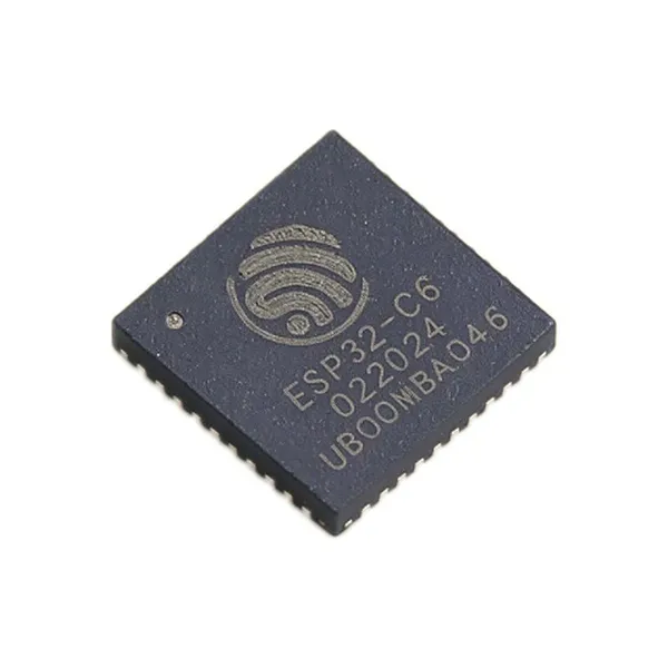
ESP32-C6 RISC-V WiFi 6 + Bluetooth 5.3 LE + Zigbee/Thread SoC 160MHz 512KB SRAM QFN-40 IoT Smart HomeNegotiableMOQ: 100 Units
-
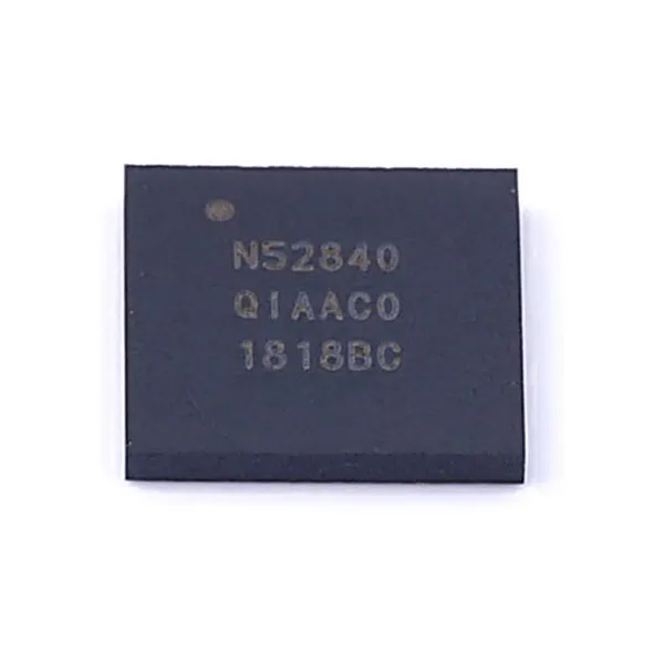
NRF52840 Nordic Bluetooth 5.3 SoC Cortex-M4F 64MHz 1MB Flash 256KB RAM AQFN-73NegotiableMOQ: 100 Units
-
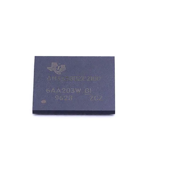
AM3358 TI Sitara AM3358BZCZ100 ARM Cortex-A8 Processor 1GHz BGA-324NegotiableMOQ: 100 Units
-
ADS1115 Texas Instruments ADS1115IDGSR 16-Bit ADC 860 SPS PGA I2C VSSOP-10NegotiableMOQ: 100 Units
-
MSP430FR5994 TI MSP430FR5994IPM Ultra-Low-Power MCU 16MHz 256KB FRAM LEA LQFP-64NegotiableMOQ: 100 Units
-
Espressif ESP32-WROOM-32D WiFi Bluetooth Module Dual-Core 240MHz 4MB Flash PCB Antenna IoTNegotiableMOQ: 100 Units
-
MSP430FR5994 TI MSP430FR5994IRGC Ultra-Low-Power MCU 16MHz 256KB FRAM LEA VQFN-64NegotiableMOQ: 100 Units
-
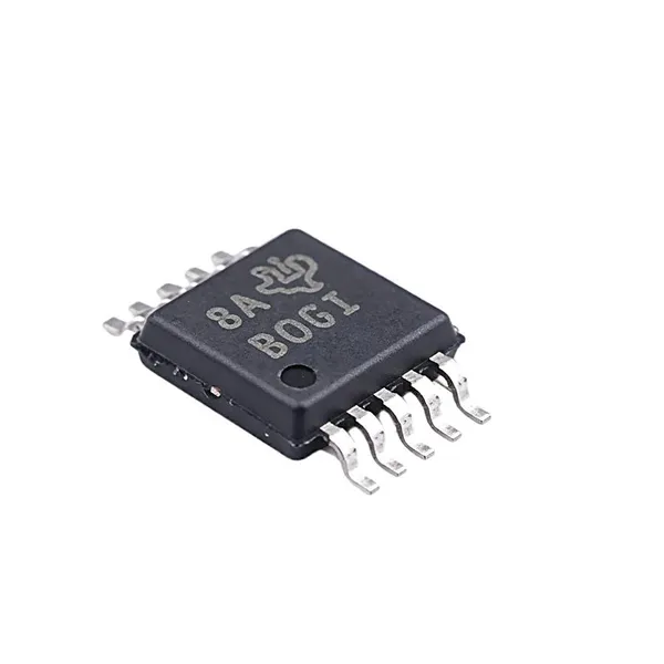
ATtiny85-20PU 8-Bit AVR Microcontroller 20MHz 8KB Flash 512B SRAM DIP-8NegotiableMOQ: 100 Units
-
Microchip ATmega2560-16AU AVR 8-Bit MCU 16MHz 256KB Flash 8KB SRAM TQFP-100NegotiableMOQ: 100 Units
-
Nordic Semiconductor NRF52832-QFAA Bluetooth 5 SoC ARM Cortex-M4F 64MHz 512KB Flash 64KB RAM QFN-48NegotiableMOQ: 100 Units
-
ATmega32U4-AU Microchip 8-Bit AVR MCU 16MHz 32KB Flash 2.5KB SRAM USB TQFP-44NegotiableMOQ: 100 Units
-
Microchip PIC16F877A-I/P 8-bit PIC MCU 20MHz 14KB Flash 368B RAM DIP-40NegotiableMOQ: 100 Units
-
STMicroelectronics STM32F103C8T6 ARM Cortex-M3 MCU 72MHz 64KB Flash 20KB SRAM LQFP-48NegotiableMOQ: 100 Units