 Business License

INA226AQDGSRQ1: A 16-Bit Current and Power Monitor for Automotive Power Rails
A power rail in an automotive system is only as reliable as the measurement behind it. When a battery management system, an ADAS domain controller or a head unit needs to know how much current a rail is drawing, the measurement has to be accurate, fast enough to catch a fault, and cheap in board space and firmware time. The INA226AQDGSRQ1 is built for exactly that job. It is the automotive qualified ordering option of Texas Instruments' INA226 current and power monitor, and it turns a shunt resistor and a bus connection into current and power readings the host can use directly.
Key Takeaways
The INA226AQDGSRQ1 measures bus voltage from 0 V to 36 V and shunt voltage over plus or minus 81.92 mV with a 16-bit ADC, and it calculates current and power on-chip. The host reads results over I2C/SMBus instead of doing the conversion in firmware.
Accuracy is held by two limits: gain error of 0.1 percent maximum and offset voltage of 10 uV maximum. Measurement error stays low even when the shunt voltage is small relative to the full range.
Integration is straightforward. The I2C/SMBus interface provides 16 programmable addresses, so several monitors can share one bus, and an alert output flags out-of-range conditions without continuous host polling. Sensing works high-side or low-side, in both current directions.
The device is AEC-Q100 qualified, operates from minus 40 degrees C to plus 125 degrees C, and comes in a VSSOP-10 package. Typical applications are HEV/EV battery management, ADAS domain controllers and automotive head units.
1. What the INA226AQDGSRQ1 measures
The INA226AQDGSRQ1 measures the voltage drop across an external shunt resistor and the voltage of the bus itself. A 16-bit ADC converts both readings, and the device calculates current from the shunt voltage and power from current and bus voltage. The host receives finished numbers over I2C/SMBus.
That on-chip calculation is the point of the part. A discrete approach needs an ADC channel on the microcontroller, a reference voltage, and firmware to turn raw counts into current and power. With the INA226AQDGSRQ1, the conversion happens inside the monitor. The microcontroller reads a result instead of building a measurement chain.
Sensing works on the high side or the low side of the load, and it measures current in both directions. One part therefore covers charge and discharge on the same rail, which is the normal case in a battery system.
2. The numbers that decide the design
Four numbers decide whether the INA226AQDGSRQ1 fits a rail. The bus voltage range is 0 V to 36 V. The shunt voltage range is plus or minus 81.92 mV. The supply voltage range is 2.7 V to 5.5 V, and quiescent current is 330 uA typical.
The package is VSSOP-10, and the operating temperature range is minus 40 degrees C to plus 125 degrees C. The AQDGSRQ1 ordering option is qualified to AEC-Q100 for automotive use.
The shunt range deserves attention at selection time. The shunt resistor value sets the voltage drop at maximum load current, and that drop has to stay inside the plus or minus 81.92 mV range. A resistor that is too large wastes power and eats into the voltage headroom. A resistor that is too small pushes the shunt voltage down toward the offset floor, where accuracy depends on the offset limit. The right value is the one that keeps the full load swing inside the range with margin at both ends.
3. Accuracy at small shunt voltages
The two accuracy limits are gain error of 0.1 percent maximum and offset voltage of 10 uV maximum. Both matter most exactly where designers want to operate: at small shunt voltages.
A small shunt resistor keeps power loss low, which is what a battery system wants. But a small resistor also produces a small voltage, and a small voltage is where offset error shows up as a percentage of the reading. A 10 uV maximum offset keeps that error small even when the shunt voltage is only a few millivolts. The 0.1 percent maximum gain error keeps the reading honest across the rest of the range.
The practical consequence is simple. If the specification calls for accurate current measurement at light load as well as full load, the offset figure is the one to check, not only the resolution. Resolution tells you the smallest step the ADC can report. Offset tells you how far that step can sit from the true value.
4. Integration: one bus, many rails
A power monitoring design rarely watches one rail. A domain controller or a battery system has several rails, and each one needs its own measurement. The INA226AQDGSRQ1 handles that with 16 programmable addresses on the I2C/SMBus interface. Several devices share one bus, and the host addresses each one in turn. No extra bus and no multiplexer is needed for the monitoring itself.
The alert output covers the second integration problem, which is fault response. It flags out-of-range conditions in hardware, so the host does not need to poll every monitor on a schedule to catch an overcurrent or undervoltage event. The host can stay in a low power state and wake only when a monitor reports a problem. For a battery system that spends much of its life waiting, that difference is real power saved.
Supply is 2.7 V to 5.5 V, so the part runs from the same rails as the surrounding logic, and 330 uA typical quiescent current keeps its own consumption small next to the loads it watches.
5. Where it fits
Three applications from the datasheet show where the INA226AQDGSRQ1 is at home. In HEV/EV battery management, it monitors current and power in high voltage battery systems, where the 0 V to 36 V bus range and the minus 40 degrees C to plus 125 degrees C operating range suit the automotive environment. In an ADAS domain controller, it monitors the power rails, where the alert output and the I2C/SMBus interface support system level power supervision. In an automotive head unit, it monitors current and power in a compact board, where the 2.7 V to 5.5 V supply range and the small VSSOP-10 package fit the space available.
The common thread is supervision of a rail that matters. Where the current reading is only a rough indicator, a simpler monitor is enough. Where the reading feeds a protection decision, a state of charge estimate or a power budget, the accuracy and the alert output earn their place.
6. Four checks before you order
First, confirm the bus voltage stays inside 0 V to 36 V across the whole operating range, including transients, not only at nominal voltage. Second, confirm the shunt value keeps the voltage drop inside plus or minus 81.92 mV at maximum current, with margin. Third, plan the I2C addressing before layout if more than one monitor shares the bus, and confirm the alert lines go where the host can act on them. Fourth, confirm the operating temperature range covers the enclosure temperature, not only the ambient temperature on the datasheet front page.
Pin assignment should be confirmed against the package drawing before PCB layout. The pin set covers the I2C/SMBus interface, the alert output, the shunt inputs, the bus voltage input, supply and ground.
7. A sourcing note for purchasing teams
The complete ordering code matters. INA226AQDGSRQ1 is the automotive qualified ordering option in the VSSOP-10 package. A shorter part number can point at a different qualification or package, so send the complete part number, the quantity, the packaging, the delivery region and the traceability requirements when you request a quote. Include the bus voltage, the shunt resistor value and the interface requirements for the application. Availability and delivery are confirmed against the actual request.
At QIXINWEI we check the complete ordering code line by line against the datasheet before confirming a BOM, because a single letter in the code can change the package, the qualification grade or the packing. If you are reviewing a BOM that carries a current and power monitor, send me your part list and I will check it line by line.
FAQ
Q1. What does INA226AQDGSRQ1 measure?
A1. INA226AQDGSRQ1 measures bus voltage and shunt voltage with a 16-bit ADC, and calculates current and power on-chip. It supports high-side or low-side sensing and measures current in both directions.
Q2. What are the bus and supply voltage ranges of INA226AQDGSRQ1?
A2. The bus voltage range of INA226AQDGSRQ1 is 0 V to 36 V, and the supply voltage range is 2.7 V to 5.5 V. Quiescent current is 330 uA typical.
Q3. How accurate is INA226AQDGSRQ1 at small shunt voltages?
A3. INA226AQDGSRQ1 holds gain error to 0.1 percent maximum and offset voltage to 10 uV maximum, so measurement error stays low even when the shunt voltage is small relative to the full range.
Q4. How does INA226AQDGSRQ1 communicate with the host?
A4. INA226AQDGSRQ1 uses an I2C/SMBus interface with 16 programmable addresses, so several devices can share one bus. It also has an alert output for out-of-range conditions.
Q5. Can INA226AQDGSRQ1 measure current in both directions?
A5. Yes. INA226AQDGSRQ1 measures current in both directions, so one device covers charge and discharge on the same rail.
Q6. What package does INA226AQDGSRQ1 use, and what is its operating temperature range?
A6. INA226AQDGSRQ1 is supplied in the VSSOP-10 package and operates from minus 40 degrees C to plus 125 degrees C. The ordering option is AEC-Q100 qualified for automotive use.
Q7. Where is INA226AQDGSRQ1 typically used?
A7. Typical applications for INA226AQDGSRQ1 are HEV/EV battery management, ADAS domain controllers and automotive head units, where accurate current and power monitoring supports protection and power supervision.
Q8. What information should an RFQ for INA226AQDGSRQ1 include?
A8. An RFQ for INA226AQDGSRQ1 should specify the complete part number, quantity, required packaging, delivery region and traceability requirements, plus the bus voltage, shunt resistor and interface requirements for the application.
Recently Posted
-
ATmega32U4-AU: Microchip 8-Bit AVR MCU with Native USB
November 18, 2026Key TakeawaysWhat it is: The ATmega32U4-AU is Microchip's 8-bit AVR microcontroller with a built-in USB 2.0 device controller,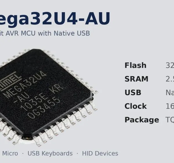 Read More
-
DRV8889QWRGERQ1: TI Automotive Stepper Driver with 1/256 Microstepping
November 14, 2026Key TakeawaysThe DRV8889QWRGERQ1 is a Texas Instruments AEC-Q100 qualified stepper motor driver for automotive bipolar stepper mot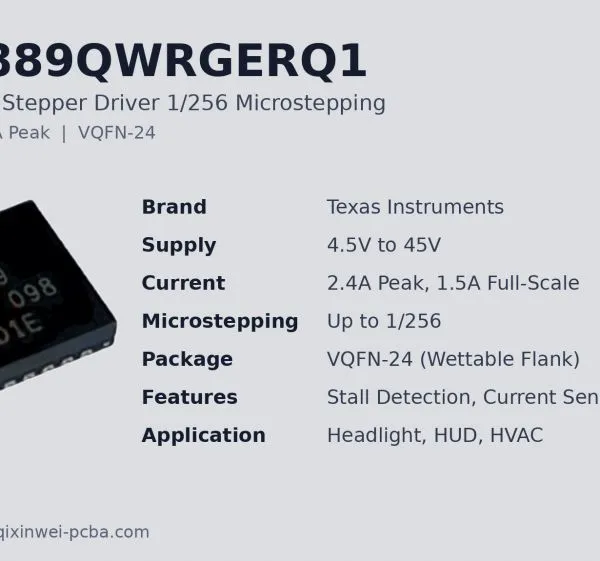 Read More
-
STC89C52 vs AT89S52: Two Classic 8051 MCUs — Which One Should You Choose?
November 12, 2026By QIXINWEI | STC89C52 vs AT89S52 | Classic 8051 MCU ComparisonThe STC89C52 and the AT89S52 look alike on paper: the same name str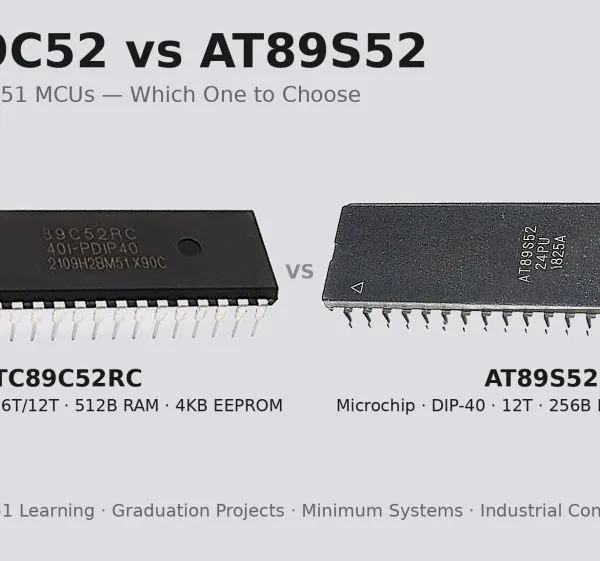 Read More
-
LM317 Adjustable Voltage Regulator: Design Guide & Circuits
November 12, 2026By QIXINWEI | TI LM317 | Adjustable Voltage RegulatorKey TakeawaysThe LM317 is a three-terminal adjustable positive voltage regula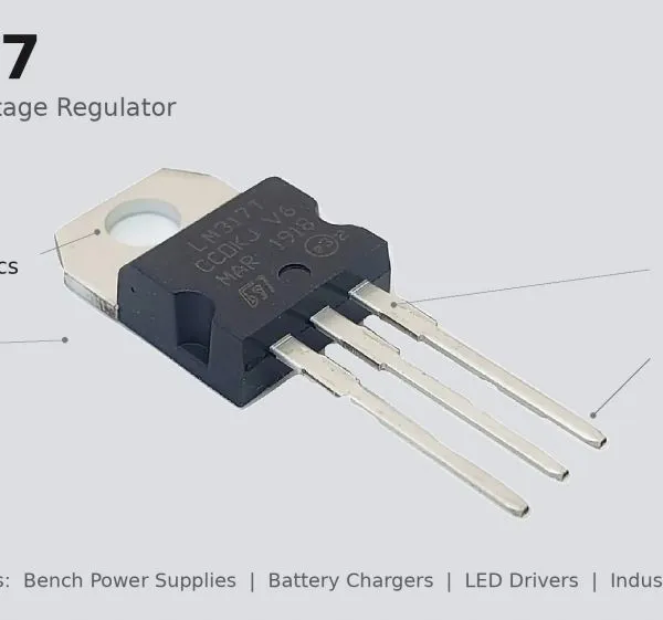 Read More

Contact Us
Recommended Products
-
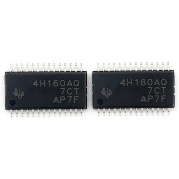
 TPS4H160BQPWPRQ1 Original TI Automotive Quad-Channel 160mOhm Smart High-Side Switch HTSSOP-28NegotiableMOQ: 100 Units
-
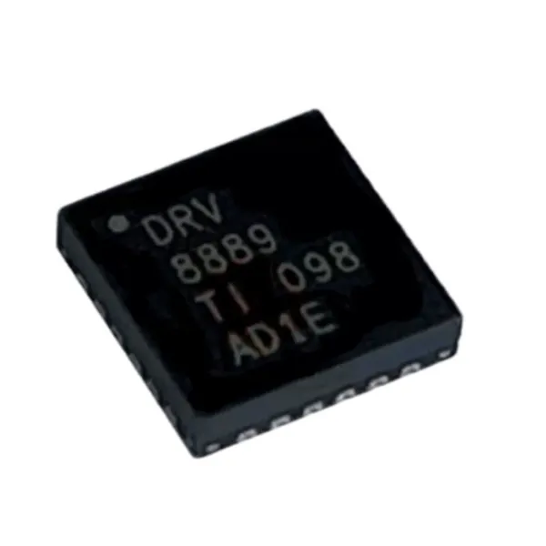
DRV8889QWRGERQ1 Original TI Automotive Stepper Motor Driver 2.4A 45V VQFN-24NegotiableMOQ: 100 Units
-
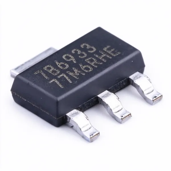
TPS7B6933QDCYRQ1 Original TI Automotive 3.3V 150mA 40V LDO Linear Regulator SOT-223NegotiableMOQ: 100 Units
-
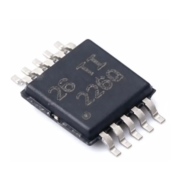
INA226AQDGSRQ1 Original TI Automotive 36V 16-Bit I2C Current Power Monitor VSSOP-10NegotiableMOQ: 100 Units
-
TPS7A6650QDGNRQ1 Original TI Automotive 150mA 40V LDO Linear Regulator 5V Fixed Output HVSSOP-8NegotiableMOQ: 100 Units
-
Microchip PIC18F4550-I/P 8-Bit MCU 48MHz 32KB Flash USB 2.0 DIP-40NegotiableMOQ: 100 Units
-
Espressif ESP32-C3 RISC-V WiFi Bluetooth LE Microcontroller 160MHz 400KB SRAM QFN-32NegotiableMOQ: 100 Units
-
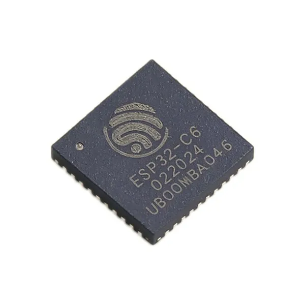
ESP32-C6 RISC-V WiFi 6 + Bluetooth 5.3 LE + Zigbee/Thread SoC 160MHz 512KB SRAM QFN-40 IoT Smart HomeNegotiableMOQ: 100 Units
-
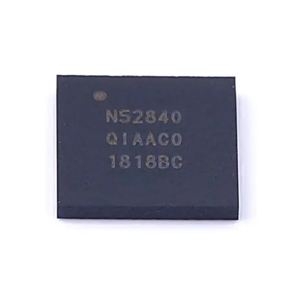
NRF52840 Nordic Bluetooth 5.3 SoC Cortex-M4F 64MHz 1MB Flash 256KB RAM AQFN-73NegotiableMOQ: 100 Units
-
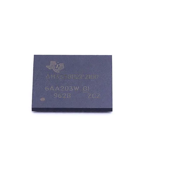
AM3358 TI Sitara AM3358BZCZ100 ARM Cortex-A8 Processor 1GHz BGA-324NegotiableMOQ: 100 Units
-
ADS1115 Texas Instruments ADS1115IDGSR 16-Bit ADC 860 SPS PGA I2C VSSOP-10NegotiableMOQ: 100 Units
-
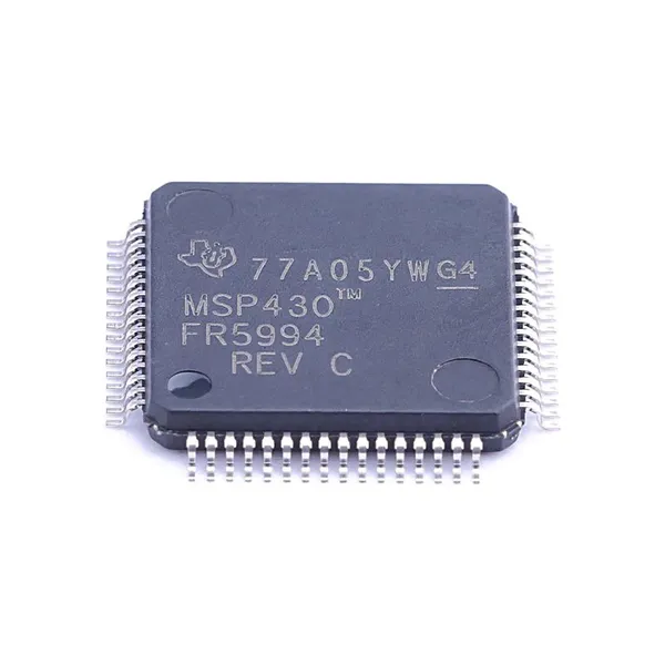
MSP430FR5994 TI MSP430FR5994IPM Ultra-Low-Power MCU 16MHz 256KB FRAM LEA LQFP-64NegotiableMOQ: 100 Units
-
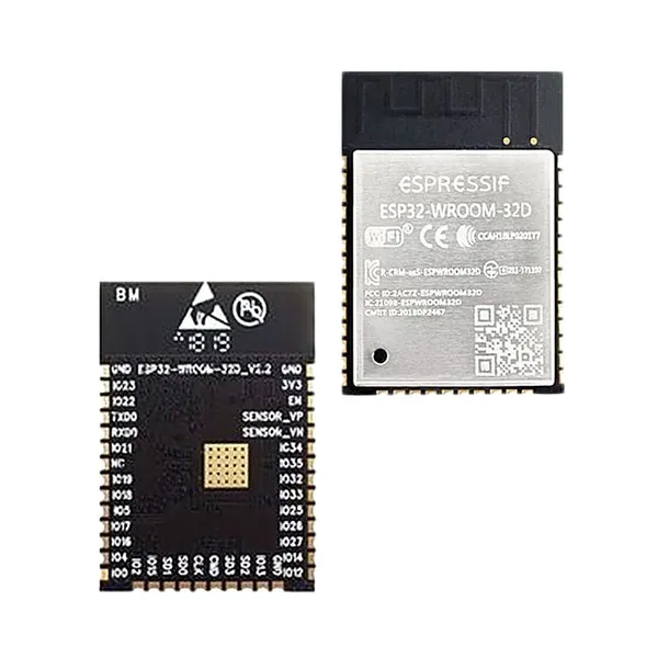
Espressif ESP32-WROOM-32D WiFi Bluetooth Module Dual-Core 240MHz 4MB Flash PCB Antenna IoTNegotiableMOQ: 100 Units
-
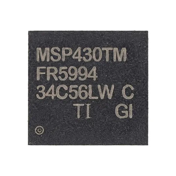
MSP430FR5994 TI MSP430FR5994IRGC Ultra-Low-Power MCU 16MHz 256KB FRAM LEA VQFN-64NegotiableMOQ: 100 Units
-
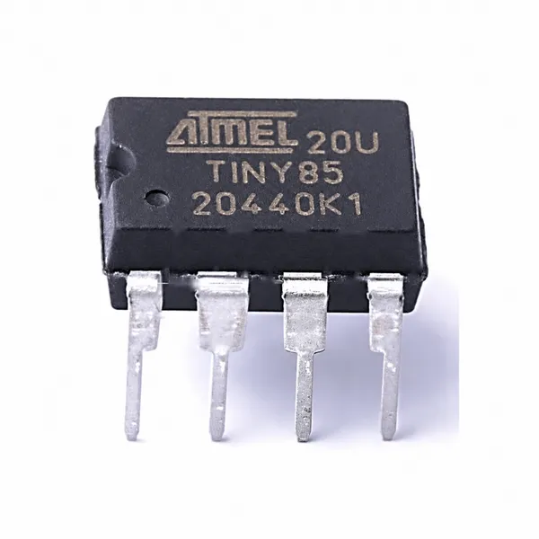
ATtiny85-20PU 8-Bit AVR Microcontroller 20MHz 8KB Flash 512B SRAM DIP-8NegotiableMOQ: 100 Units
-
Microchip ATmega2560-16AU AVR 8-Bit MCU 16MHz 256KB Flash 8KB SRAM TQFP-100NegotiableMOQ: 100 Units
-
Nordic Semiconductor NRF52832-QFAA Bluetooth 5 SoC ARM Cortex-M4F 64MHz 512KB Flash 64KB RAM QFN-48NegotiableMOQ: 100 Units
-
ATmega32U4-AU Microchip 8-Bit AVR MCU 16MHz 32KB Flash 2.5KB SRAM USB TQFP-44NegotiableMOQ: 100 Units
-
Microchip PIC16F877A-I/P 8-bit PIC MCU 20MHz 14KB Flash 368B RAM DIP-40NegotiableMOQ: 100 Units
-
STMicroelectronics STM32F103C8T6 ARM Cortex-M3 MCU 72MHz 64KB Flash 20KB SRAM LQFP-48NegotiableMOQ: 100 Units