 Business License

LM317 Adjustable Voltage Regulator: Design Guide & Circuits
By QIXINWEI | TI LM317 | Adjustable Voltage Regulator
Key Takeaways
The LM317 is a three-terminal adjustable positive voltage regulator from Texas Instruments, delivering 1.25V to 37V at up to 1.5A with only two external resistors setting the output voltage.
The output voltage follows one formula: VOUT = 1.25V × (1 + R2/R1) + IADJ × R2. With the standard R1 of 240Ω, a 720Ω R2 gives 5V and a 2.1kΩ R2 gives 12V.
Heat is the number one design risk. Power dissipation equals (VIN − VOUT) × IOUT, and a TO-220 LM317 without a heatsink can only shed about 2W before thermal shutdown.
The LM317 needs at least 3.5mA of load current to stay in regulation, and the input must sit at least 2V above the output. Ignore either rule and the output drifts.
For bulk supply and BOM matching of original TI LM317 regulators, QIXINWEI supports prototype quantities through production volumes.
What the LM317 Is, and Why It Is Still Everywhere
The LM317 has been in production since 1997, and it is still one of the most searched voltage regulators in the world, with around 40,500 Google searches a month. The reason is simple: it does one job with almost no supporting parts. Three pins, two resistors, and you have a regulated power rail at any voltage from 1.25V to 37V.
Unlike a fixed regulator such as the LM7805, which only gives you 5V, the LM317 lets the designer choose the output. That flexibility is why it shows up in bench power supplies, battery chargers, LED drivers, audio equipment, industrial control boards, and thousands of hobbyist projects. It is also a forgiving part: internal current limiting, thermal overload protection, and safe-area compensation are built in, so most wiring mistakes result in a hot chip rather than a dead one.
The LM317 is a linear regulator, not a switching regulator. It burns the voltage difference between input and output as heat. That makes it quiet, with no switching noise, and ideal for analog circuits, audio, and sensor front ends. It also means thermal design is not optional, which is where most LM317 circuits go wrong.
LM317 Key Specifications
Manufacturer: Texas Instruments
Regulator type: Adjustable three-terminal positive linear voltage regulator
Output voltage range: 1.25V to 37V, adjustable
Output current: 1.5A maximum
Input-to-output differential: 3V to 40V
Reference voltage: 1.25V
Line regulation: 0.01%/V typical
Load regulation: 0.1% typical
Dropout voltage: 2.0V typical
Minimum load current: 3.5mA typical, 10mA maximum
ADJUST pin current: 50µA to 100µA
PSRR: 80dB at 120Hz with CADJ = 10µF
Operating junction temperature: 0°C to 125°C
Protection: Internal short-circuit current limiting, thermal overload protection, safe-area compensation
Packages: TO-220 (KC, KCS, KCT), TO-263 (KTT), SOT-223 (DCY)
Variants: LM317A (higher accuracy), LM317HV (60V input, 1.5A)
How to Set the Output Voltage of the LM317
The LM317 holds 1.25V between its OUTPUT pin and its ADJUST pin. Two resistors form a divider that sets the output. R1 connects between OUTPUT and ADJUST, R2 connects between ADJUST and ground. The formula is:
VOUT = 1.25V × (1 + R2 / R1) + IADJ × R2
The IADJ term is small, typically 50µA, so in practice most designers use the simplified version VOUT = 1.25V × (1 + R2 / R1). The standard value for R1 is 240Ω. That is not arbitrary: 1.25V across 240Ω draws 5.2mA, which satisfies the minimum load current requirement and keeps the regulator in regulation even with no external load.
Common output voltages with R1 = 240Ω:
3.3V output: R2 = 390Ω
5V output: R2 = 720Ω
9V output: R2 = 1.5kΩ
12V output: R2 = 2.1kΩ
15V output: R2 = 2.6kΩ
24V output: R2 = 4.4kΩ
For a continuously adjustable bench supply, replace R2 with a 5kΩ potentiometer in series with a 240Ω fixed resistor. The potentiometer alone can swing the output from 1.25V up to about 27V with a 30V input, and the fixed resistor guarantees the output never drops below the 1.25V floor.
Two capacitors are worth adding. A 0.1µF ceramic capacitor at the input, close to the regulator, prevents oscillation when the input leads are long. A 1µF capacitor at the output improves transient response. If you need the full 80dB ripple rejection, add a 10µF capacitor from the ADJUST pin to ground; this bypasses the ripple that would otherwise appear at the output through the divider.
Five LM317 Design Mistakes That Kill the Circuit
1. Ignoring heat dissipation
This is the most common LM317 failure. Power dissipation is (VIN − VOUT) × IOUT. A 24V input dropping to 5V at 1A burns 19W. A bare TO-220 package has a junction-to-ambient thermal resistance of about 23°C/W, so without a heatsink it can only dissipate roughly 2W before the junction hits its 125°C limit and the thermal protection shuts the part down. If the voltage drop is large or the current is high, use a heatsink, or use a switching pre-regulator to drop most of the voltage first.
2. Forgetting the minimum load current
The LM317 needs at least 3.5mA flowing through it to maintain regulation, and up to 10mA in the worst case. With R1 = 240Ω, the divider itself draws 5.2mA, which covers the typical case. If you use a much larger R1 to save power, the divider current drops below the minimum, and the output voltage rises above the set value when the external load is light or disconnected. Keep R1 at 240Ω, or add a bleed resistor at the output.
3. Running the input too close to the output
The LM317 needs about 2V of headroom between input and output. A 5V output needs at least 7V at the input, and that is before accounting for input ripple. If the input is a rectified transformer supply, the ripple troughs can dip below the dropout threshold even when the average voltage looks fine, and the output will carry the ripple straight through. Allow at least 3V of headroom in practice.
4. Placing the ADJUST resistor far from the chip
The ADJUST pin is a high-impedance node. Long traces between the regulator and the divider pick up noise, and the IADJ current flowing through that trace creates a voltage error. Keep R1 and R2 close to the LM317, with short, direct traces. Ground the bottom of R2 at the same point as the load ground, not at a distant ground plane connection, or ground current will shift the output voltage.
5. Skipping protection diodes on large output capacitors
If the output has a large capacitor and the input is shorted or disconnected, the output capacitor discharges back through the regulator, and the resulting current can damage the chip. TI recommends a protection diode from output to input when the output capacitance exceeds about 25µF, and a second diode across R2 when the ADJUST bypass capacitor exceeds 10µF. For most small circuits these diodes are unnecessary, but for supplies with large output capacitors they are cheap insurance.
LM317 vs Fixed Regulators: When Adjustable Wins
LM317 vs LM7805: The LM7805 gives a fixed 5V output with no external resistors, and it is simpler when 5V is all you need. The LM317 wins whenever the voltage is not 5V, when you need a variable output, or when you want the same part across multiple rails in a product line. The LM317 also has better line and load regulation in most configurations.
LM317 vs LM317A: The LM317A is a pin-compatible higher-accuracy version with tighter reference voltage tolerance. Use it when the output voltage must be precise, for example in measurement equipment or reference supplies. For most general-purpose designs the standard LM317 is sufficient.
LM317 vs LM317HV: The LM317HV handles up to 60V input instead of 40V. Use it for high-voltage rails, for example 48V industrial supplies stepped down to 24V or 12V. The rest of the design rules are identical.
LM317 vs switching regulators: A switching regulator is far more efficient when the voltage drop is large, but it adds switching noise, a more complex layout, and an inductor. The LM317 is the better choice for low-noise analog supplies, audio circuits, and low-current rails where the heat is manageable.
LM317 Package Options
TO-220 (KC, KCS, KCT): Through-hole, 1.5A, the classic version. Easy to mount on a heatsink, the right choice for bench supplies and prototypes.
TO-263 (KTT): Surface-mount D2PAK, 1.5A. The PCB copper pour acts as the heatsink, good for production boards with adequate copper area.
SOT-223 (DCY): Compact surface-mount, lower current in practice because of limited heat dissipation. Best for low-current rails under 500mA where board space matters.
Where the LM317 Fits
Bench power supplies: The classic LM317 application. A transformer, bridge rectifier, and LM317 with a potentiometer gives a variable 1.25V to 30V supply for the lab.
Battery chargers: The adjustable output and current-limiting behaviour make the LM317 a simple constant-voltage charger for lead-acid and NiMH packs.
LED drivers: Wired as a constant-current source, the LM317 drives LED strings with a single resistor setting the current.
Audio and analog supplies: The low noise and high ripple rejection suit preamplifiers, DACs, and sensor front ends.
Industrial control boards: The wide 1.25V to 37V range covers 3.3V, 5V, 12V, and 24V rails from a single part number, simplifying BOM and inventory.
Post-regulation: Placing an LM317 after a switching regulator cleans up the switching ripple and gives a quiet rail for sensitive analog sections.
LM317 FAQ
What is the LM317 output voltage range?
The LM317 output is adjustable from 1.25V to 37V, set by two external resistors. The input voltage must be at least 2V above the desired output, and the input-to-output differential must not exceed 40V.
How do I calculate the LM317 resistor values?
Use VOUT = 1.25V × (1 + R2 / R1). With the standard R1 of 240Ω, R2 is 720Ω for 5V, 2.1kΩ for 12V, and 390Ω for 3.3V. Keep R1 at 240Ω so the divider draws 5.2mA and satisfies the minimum load current.
Why does my LM317 get hot?
Heat is (VIN − VOUT) × IOUT. A 24V input to 5V output at 1A dissipates 19W, far beyond what a bare TO-220 can shed. Add a heatsink, reduce the input voltage, or use a switching pre-regulator to drop most of the voltage before the LM317.
Why is my LM317 output voltage too high with no load?
The LM317 needs a minimum load current of 3.5mA, up to 10mA worst case. If R1 is too large, the divider current falls below this and the output drifts high. Use R1 = 240Ω, or add a bleed resistor at the output.
Can the LM317 be used as a current regulator?
Yes. Connect a single resistor between the OUTPUT and ADJUST pins, and the LM317 holds 1.25V across it, giving a constant current of 1.25V / R. This is the standard circuit for LED drivers and simple battery chargers.
What is the difference between LM317 and LM317A?
The LM317A is a pin-compatible version with tighter reference voltage tolerance and better accuracy. Use it when output precision matters, such as in measurement equipment. For general-purpose designs the standard LM317 is sufficient and usually cheaper.
Sourcing the LM317 from QIXINWEI
QIXINWEI supplies original Texas Instruments LM317 regulators in TO-220, TO-263, and SOT-223 packages, along with the LM317A and LM317HV variants, in prototype quantities through production volumes. As a full-range electronic components distributor with BOM matching service, QIXINWEI can consolidate the LM317 with the resistors, capacitors, heatsinks, and other parts on your bill of materials into a single shipment. For a quotation or availability check, contact the QIXINWEI sales team with your required package, quantity, and target price.
Supplier: Shenzhen Qixinwei Technology Co., Ltd. (QIXINWEI)
Recently Posted
-
INA226AQDGSRQ1: A 16-Bit Current and Power Monitor for Automotive Power Rails
November 20, 2026A power rail in an automotive system is only as reliable as the measurement behind it. When a battery management system, an ADAS d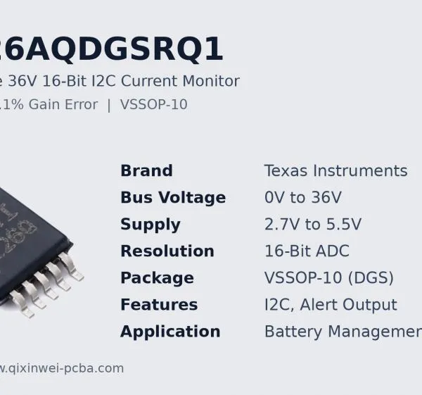 Read More
-
ATmega32U4-AU: Microchip 8-Bit AVR MCU with Native USB
November 18, 2026Key TakeawaysWhat it is: The ATmega32U4-AU is Microchip's 8-bit AVR microcontroller with a built-in USB 2.0 device controller,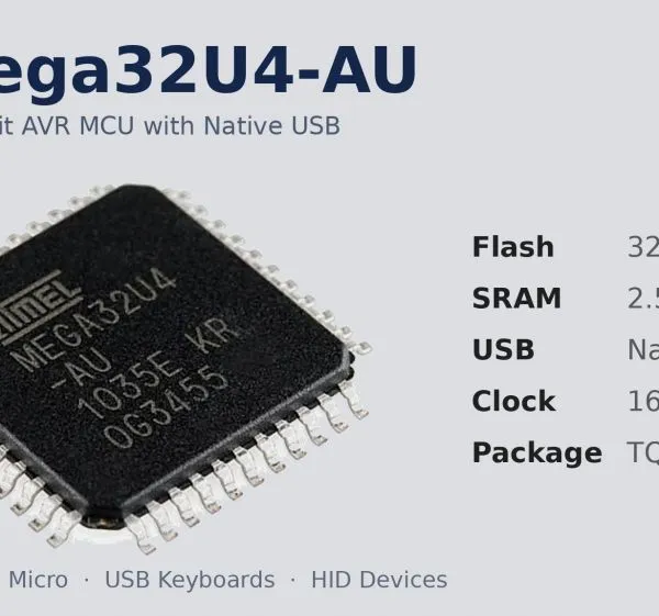 Read More
-
DRV8889QWRGERQ1: TI Automotive Stepper Driver with 1/256 Microstepping
November 14, 2026Key TakeawaysThe DRV8889QWRGERQ1 is a Texas Instruments AEC-Q100 qualified stepper motor driver for automotive bipolar stepper mot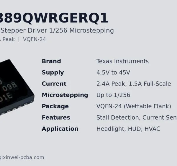 Read More
-
STC89C52 vs AT89S52: Two Classic 8051 MCUs — Which One Should You Choose?
November 12, 2026By QIXINWEI | STC89C52 vs AT89S52 | Classic 8051 MCU ComparisonThe STC89C52 and the AT89S52 look alike on paper: the same name str Read More

Contact Us
Recommended Products
-
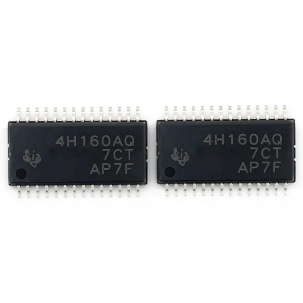
 TPS4H160BQPWPRQ1 Original TI Automotive Quad-Channel 160mOhm Smart High-Side Switch HTSSOP-28NegotiableMOQ: 100 Units
-
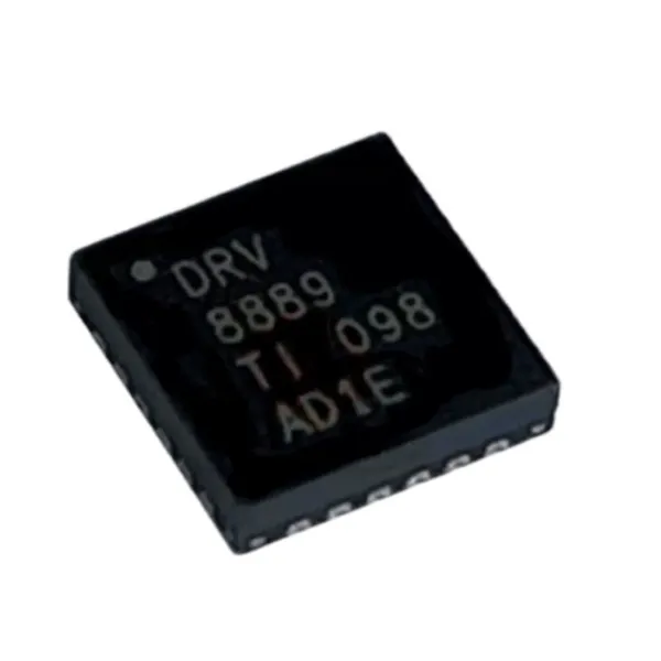
DRV8889QWRGERQ1 Original TI Automotive Stepper Motor Driver 2.4A 45V VQFN-24NegotiableMOQ: 100 Units
-
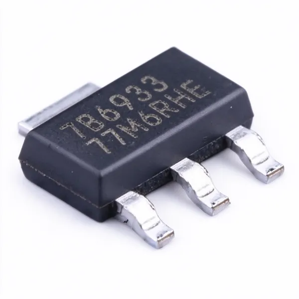
TPS7B6933QDCYRQ1 Original TI Automotive 3.3V 150mA 40V LDO Linear Regulator SOT-223NegotiableMOQ: 100 Units
-
INA226AQDGSRQ1 Original TI Automotive 36V 16-Bit I2C Current Power Monitor VSSOP-10NegotiableMOQ: 100 Units
-
TPS7A6650QDGNRQ1 Original TI Automotive 150mA 40V LDO Linear Regulator 5V Fixed Output HVSSOP-8NegotiableMOQ: 100 Units
-
Microchip PIC18F4550-I/P 8-Bit MCU 48MHz 32KB Flash USB 2.0 DIP-40NegotiableMOQ: 100 Units
-
Espressif ESP32-C3 RISC-V WiFi Bluetooth LE Microcontroller 160MHz 400KB SRAM QFN-32NegotiableMOQ: 100 Units
-
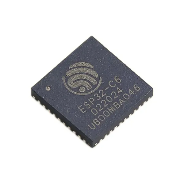
ESP32-C6 RISC-V WiFi 6 + Bluetooth 5.3 LE + Zigbee/Thread SoC 160MHz 512KB SRAM QFN-40 IoT Smart HomeNegotiableMOQ: 100 Units
-
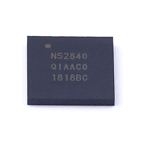
NRF52840 Nordic Bluetooth 5.3 SoC Cortex-M4F 64MHz 1MB Flash 256KB RAM AQFN-73NegotiableMOQ: 100 Units
-
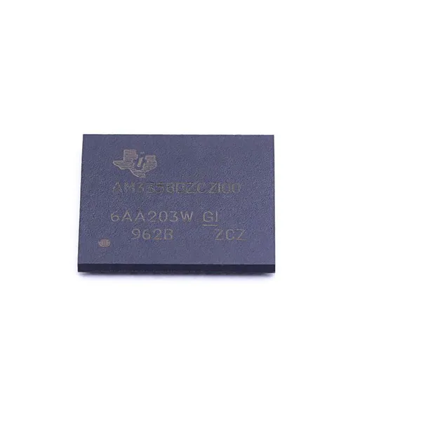
AM3358 TI Sitara AM3358BZCZ100 ARM Cortex-A8 Processor 1GHz BGA-324NegotiableMOQ: 100 Units
-
ADS1115 Texas Instruments ADS1115IDGSR 16-Bit ADC 860 SPS PGA I2C VSSOP-10NegotiableMOQ: 100 Units
-
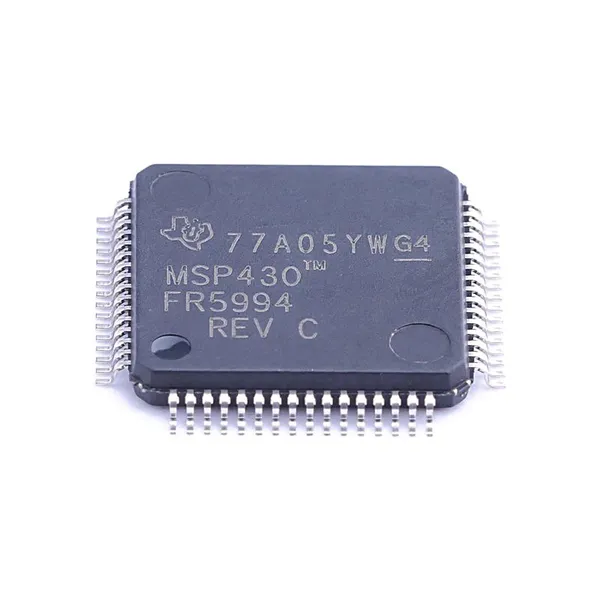
MSP430FR5994 TI MSP430FR5994IPM Ultra-Low-Power MCU 16MHz 256KB FRAM LEA LQFP-64NegotiableMOQ: 100 Units
-
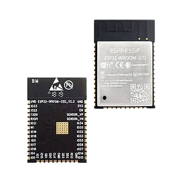
Espressif ESP32-WROOM-32D WiFi Bluetooth Module Dual-Core 240MHz 4MB Flash PCB Antenna IoTNegotiableMOQ: 100 Units
-
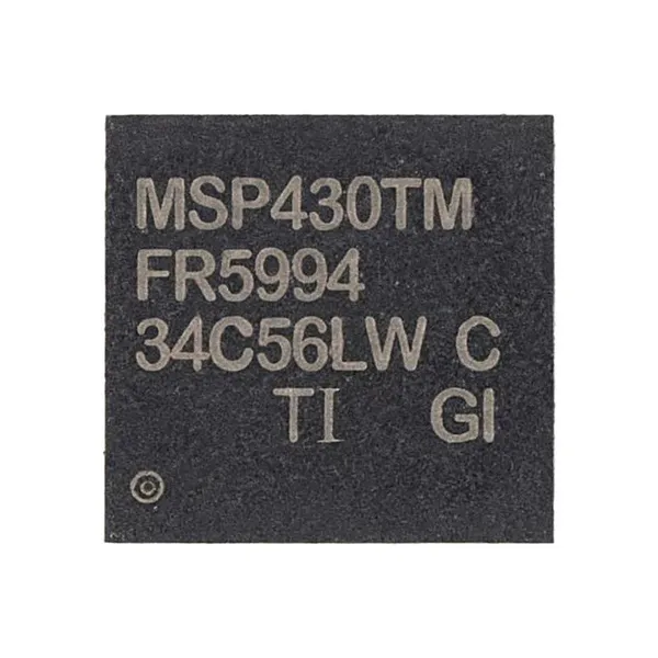
MSP430FR5994 TI MSP430FR5994IRGC Ultra-Low-Power MCU 16MHz 256KB FRAM LEA VQFN-64NegotiableMOQ: 100 Units
-
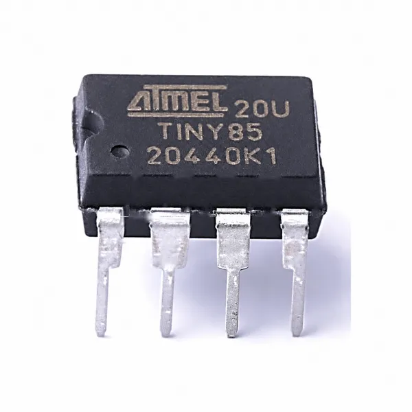
ATtiny85-20PU 8-Bit AVR Microcontroller 20MHz 8KB Flash 512B SRAM DIP-8NegotiableMOQ: 100 Units
-
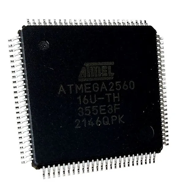
Microchip ATmega2560-16AU AVR 8-Bit MCU 16MHz 256KB Flash 8KB SRAM TQFP-100NegotiableMOQ: 100 Units
-
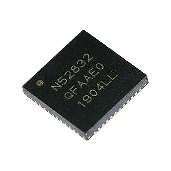
Nordic Semiconductor NRF52832-QFAA Bluetooth 5 SoC ARM Cortex-M4F 64MHz 512KB Flash 64KB RAM QFN-48NegotiableMOQ: 100 Units
-
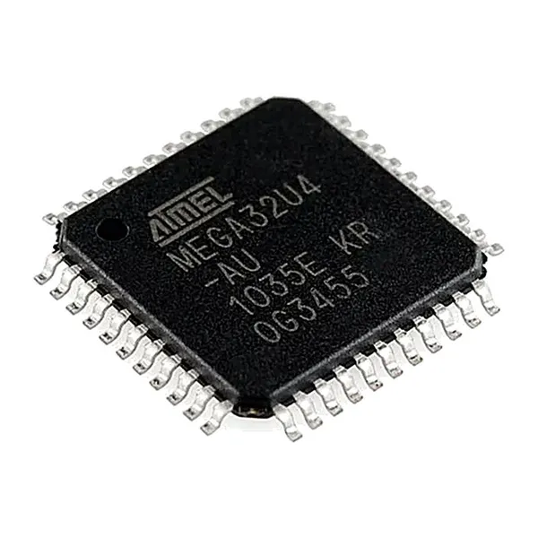
ATmega32U4-AU Microchip 8-Bit AVR MCU 16MHz 32KB Flash 2.5KB SRAM USB TQFP-44NegotiableMOQ: 100 Units
-
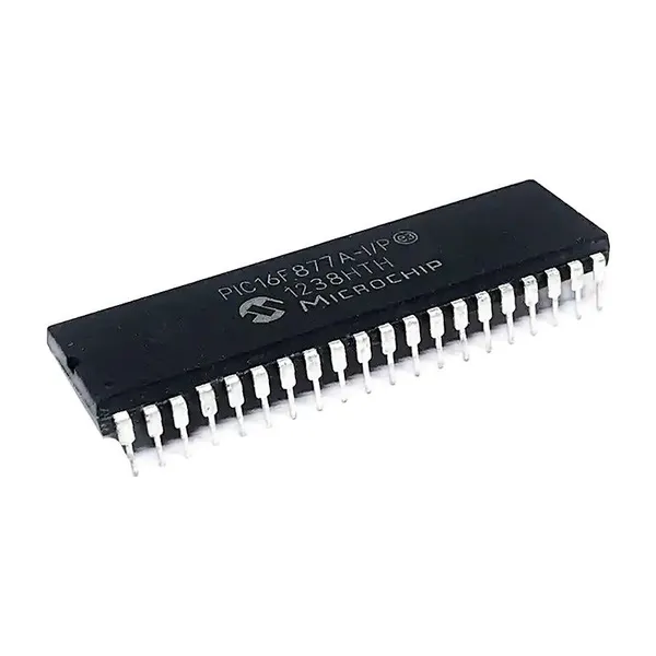
Microchip PIC16F877A-I/P 8-bit PIC MCU 20MHz 14KB Flash 368B RAM DIP-40NegotiableMOQ: 100 Units
-
STMicroelectronics STM32F103C8T6 ARM Cortex-M3 MCU 72MHz 64KB Flash 20KB SRAM LQFP-48NegotiableMOQ: 100 Units